
Project-Management
| Name | Working area(s) | Contact | |
|---|---|---|---|

| Dipl.-Ing. Martin Hallas Gas-insulated HVDC systems |
Presentation of the HVDC test hall in Griesheim
Opening of the new HVDC test laboratory in Griesheim
Background
DC or AC? The question already existed between Edison and Tesla at the end of the 19th century. At that time, alternating current won the discussion because it can be transformed to high voltages and thus transported over long distances with little losses. Today in the 21st century the question arises again. AC reaches its limits over long distances, as cable systems in particular can only cover short distances due to their high need for reactive power.
The short range of underground alternating voltage systems is a hurdle that will arise in the future energy supply in Germany. Due to the expansion of renewable energies, greater capacities have to be transported over long distances from the windy north to the industrially strong south of Germany. A large part of the population favors underground lines over conventional overhead lines. A possible solution to solve this problem and an alternative to cables: Gas-insulated DC voltage systems. These offer several advantages over classic cable systems, for example:
- Compactness of a gas-insulated system
- Higher current carrying capacity due to the better convection within the system
- Significantly reduced transmission width compared to cable systems of the same performance due to the higher current carrying capacity
- Self-healing isolation during operation
- Short-circuit proof installation
- No weak points due to connection sleeves
Motivation
The success of the german energy transition is directly related to the expansion of the electrical grid in Germany. The use of wind energy in northern Germany means that large amounts of electricity have to be transported from the north to the main consumption areas in southern Germany.
For the implementation of this project and for the grid integration of renewable energies, underground lines are favored by politics and the population. With the existing alternating current technology, however, it is hardly technically and economically feasible to run underground lines over several 100 km. New long-distance transmission technologies must therefore be researched in order to secure Germany's future energy supply.
Gas-insulated direct current transmission lines (“DC GIL” – Direct Current Gas-insulated Transmission Lines) represent a promising approach to solve the problem.
DC GIL
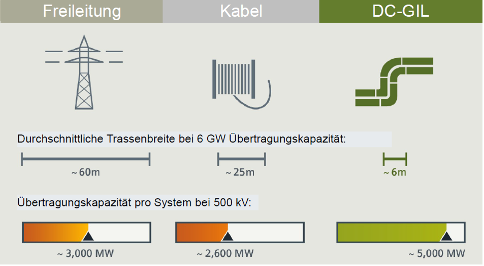
Compared to other technologies, DC GIL offers the advantage that high transmission capacities can be achieved with significantly reduced transmission widths. Figure 1 shows the relationships. Overhead lines can transmit approx. 3000 MW of power over a transmission width of 60 meters. This corresponds roughly to the width of a soccer field. With DC GIL, on the other hand, due to the high current carrying capacity and the compact design, 5000 MW can be laid over a width of 6 meters. This corresponds to the transmission of an output of 4 to 5 large power plant blocks the width of a football goal.
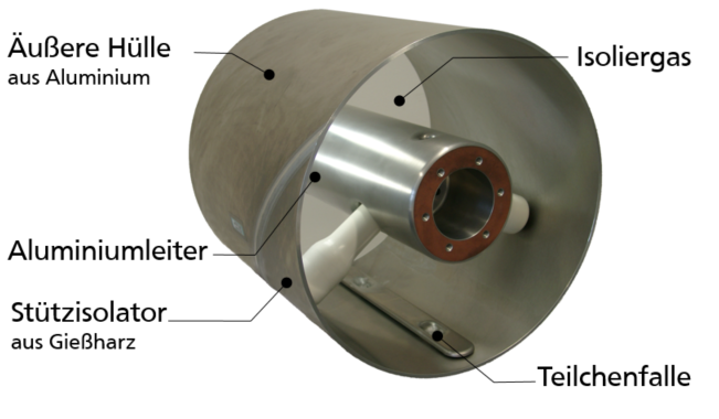
When gas-insulated direct current transmission technology is ready for use, parts of the transmission lines through Germany could be implemented underground on the one hand, and much more compact and economical on the other than with the technologies currently being considered (overhead lines, cables). The positive consequences would be a significantly reduced use of the landscape and less visibility. A gas-insulated line consists of a metallic enclosure and a metallic inner conductor. The enclosure ensures that the insulating gas inside the GIL can be under pressure, and it prevents the occurrence of electrical fields outside the line. The central inner conductor is on high voltage and is supported by solid insulators. These consist of cast resin and belong to the newly developed components within the line especially for DC voltage. The components are pre-assembled and welded together on site. The basic structure of a GIL is shown in Figure 2.
„DC CTL DBI“: Research in Griesheim
In this project, the novel gas-insulated direct current transmission lines are researched. For this purpose, a test facility is being built especially for the project, in which the world's first DC GIL (manufacturer: Siemens) with a total length of 250 m, partly directly buried, is subjected to a long-term test under realistic operating conditions. The test hall and the testing technology will be built by TU Darmstadt, the DC GIL device under test by Siemens AG.
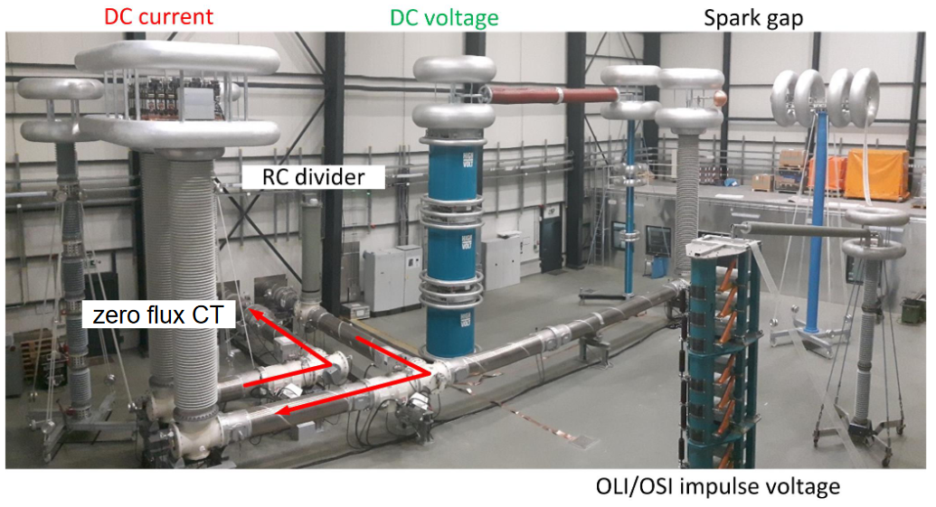
All dielectric tests are carried out by the TU Darmstadt. All high-voltage test facilities are housed in the specially built test hall. This includes a direct voltage and a direct current source as well as the entire measurement and testing technology. There is also space for a impulse voltage generator to generate overvoltages. Figure 3 gives an overview. The technical data of the test system is:
| DC nominal voltage GIL | ±500 kV |
| DC nominal current GIL | 5000 A |
| Max. DC test voltage („U“) | ±825 kV |
| Max. impulse voltage („OSI“/„OLI“) | 1425 kV |
| DC nominal testing current („I“) | 5000 A |
In addition to the first DC GIL worldwide, a new test technology is also being developed in the project. For dielectric testing of the GIL under realistic conditions, for example, a voltage of 550 kV with a current of 5000 A is necessary, which corresponds to an output of 2.75 GW. Three large power plant blocks would be required to provide this capacity. In order to reduce this requirement to the output of a 200 HP motor, a “synthetic” test method was developed, where the voltage and current are generated and injected separately with a new type of generator (patent pending by TU Darmstadt).
Overvoltages in the grid caused by switching operations or lightning strikes are tested with surge voltages. In this project, these overvoltages are switched directly to the test object when DC voltage is applied. This test technology is also a new development. For the first time, oscillating impulse voltage (OLI, OSI) is used, because otherwise surge tests on such electrically long lines would be difficult to realize.
The DC GIL device under test is being built in Griesheim by Siemens AG for the first time under real construction site conditions. Investigations in the field of soil mechanics on the underground part of the test road are planned as a further research focus. For this purpose, the geotechnical experts around Prof. Dr.-Ing. Thomas Neidhart of the Ostbayerischen Technische Hochschule Regensburg (OTH Regensburg) extensiometer and glass fibers are used to determine the thermal expansion of the DC GIL in long-term operation and the forces on the pipes in the ground are determined. The temperatures inside and outside the DC GIL during the various operating states are also determined by the OTH Regensburg and the calculation methods are verified by this practical test.
For the condition assessment of the DC GIL, the researchers from the TU Darmstadt in cooperation with other experts from the TU Berlin around Prof. Dr.-Ing. Roland Plath and with measurement technology companies so-called partial discharge measurements carried out and continuously evaluated during high-voltage operation.
The test program forms a long-term test with the simulation of real electrical, thermal and mechanical operating conditions, which qualifies this line technology as an option for the transmission of electrical energy.
This makes a decisive contribution to the success of the energy transition in general.
Major part of the work
The focus of this work lies in the development of the test technology, as well as the planning and implementation of a suitable long-term test for gas-insulated HVDC systems. The long-term test is intended to map the later operation of such systems, which is typically specified in the range of approx. 40 years. The planned experiments are structured as follows:
- Endurance tests to investigate the long-term operating behavior
- Superimposed surge voltage tests to simulate the fault
In order to be able to simulate the nominal operation during the test, the system must be operated with current and voltage at the same time. The supply with electrical current ensures the heating of the system, the supply with electrical voltage ensures dielectric stress and polarization of the insulation. The current heat also influences the electric field distribution within the solid insulators of gas-insulated HVDC systems. The field grading of the solid insulators takes place resistively via the (very high) ohmic resistance. This is temperature-dependent, which means that negative influences can occur due to the combination of current and voltage. According to this, real service operation can only be tested if current and voltage are applied to the GIL at the same time.
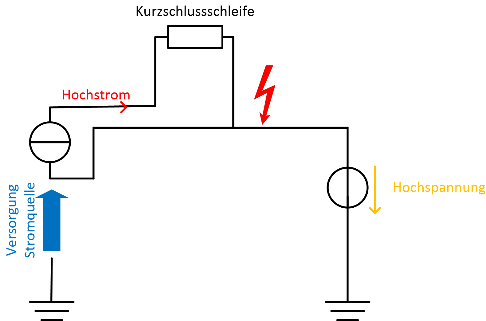
The greatest challenge with this requirement lies in the testing technology, in particular in the current injection on high voltage potential. For this purpose, a power source must work at high voltage potential and generate a rectified high current. At the same time, the power source must be supplied from earth via a transmission path. The entire system must work for DC voltage. There are no known test systems or generators of this type.
[1] Siemens AG – Gas-insulated transmission lines, website: Siemens.com/GIL
The TU Darmstadt thanks the IWB-EFRE program of the state of Hessen (funding code 20002558) for the great support of this work.
Siemens AG, Business Unit “Transmission Solutions” thanks the Federal Ministry for Economic Affairs and Energy for the great support of the research work in the project “DC CTL DBI” (funding code: 03ET7546)