Project-Management
| Name | Working area(s) | Contact | |
|---|---|---|---|

| Michael Kempf M.Sc. Investigation of the dielectric and thermal properties of solid insulating materials under HFHV stress | michael.kempf@tu-... +49 6151 16-20445 S3|21 410 |
Background
Both in high voltage engineering and in power elec- tronics, the requirements for insulating materials are increasing rapidly as a result of an increasing combi- nation of high electric field strengths and high fre- quencies simultaneously.
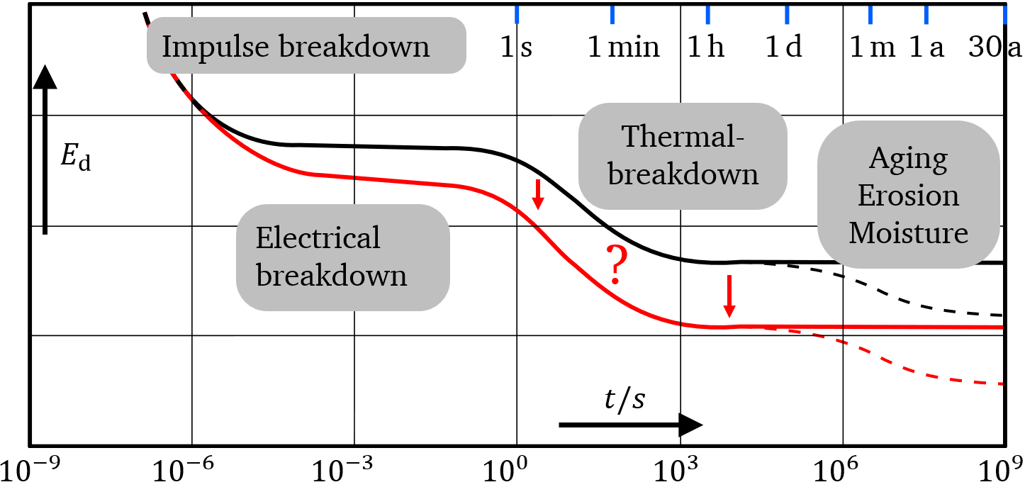
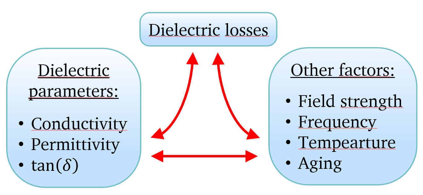
It is already known that the dielectric losses increase both with increasing field strength and with increa- sing frequencies. As a result, the insulation materials thermal behavior is negatively influenced, which may result in a lower dielectric strength and an accelera- ted aging process. This could mean that known lifetime characteristicscan not be transferred to the future requirements.
For these reasons, further electrical, thermal and material-scientific investigations are urgently required in order to be able to make systematic statements about the robustness, the insulation failure and the aging of insulating materials. In particular, the frequency, field strength and temperature dependent dielectric loss mechanisms requires a more in-depth under-standing.
Objectives
The current knowledge of the behavior of insulating materials up to a frequency range of a few MHz in combination with high electric fields, as reached by modern power electronic circuits, is completely insufficient to be able to make systematic statements about the resilience, the insulation failure rate or the aging behavior. In particular, the frequency, field strength and temperature dependent dielectric loss mechanisms must be better understood.
Therefore, new approaches and methods in the form of coordinated experimental investigations and accompanying FEM-simulations on selected insulating materials with HFHV are to be conducted in this project.
The objective of the investigations is to gain a fundamentally better understanding of the complex relationships between the dielectric and thermal properties and stress factors such as frequency, field strength and temperature.
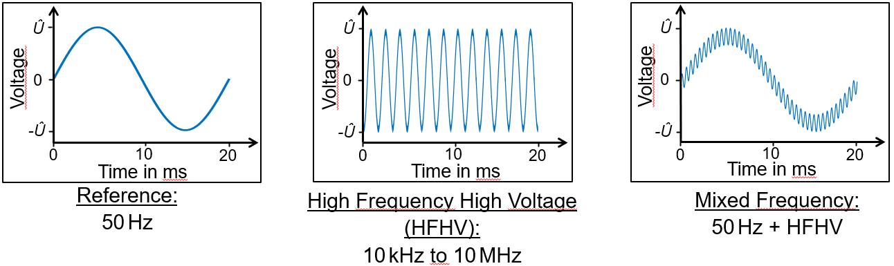
Generating high frequency high voltage (HFHV)
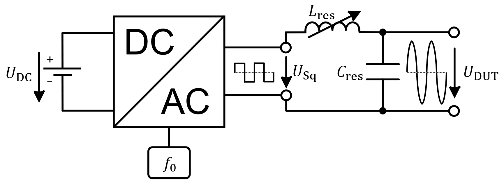
Due to the high losses, conventional high-voltage transformer with iron cores cannot be used to generate continuous HFHV with frequencies up to the MHz range and amplitudes of several kilovolts. Usually, ferrite or iron powder cores are used for transformers in medium and high-frequency techno- logy. For the planned operation they are only suitable for operating frequencies up to approx. 100 kHz. Another problem is the (thin) insulation of the individual turn of the high-voltage winding, which cannot withstand the HFHV permanently.
For frequencies above 100 kHz, resonant circuits which are fed by converters are a suitable alternative to the conventional generator of high-voltage.
Dielectric Investigations
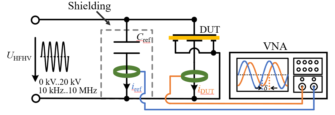
As a part of the dielectric investigations, the dissipation factor (as a parameter of the dielectric losses) as well as the permittivity or the capacitance of various insulating materials are to be determined as a function of the frequency and the applied electric field strength.
Therefore, the currents are measured both in the path of the device under test (DUT) and a reference path. The currents are evaluated using a vector-network-analyzer regarding their amplitudes and phase shift. The measurement of the HFHV is realized via a capacitive voltage divider, which consists entirely of vacuum capacitors.
The following values are determined as part of the dielectric investigations depending on different frequency-field strength combinations:
1) Loss factor
2) Relative permittivity
3) Dielectric losses
Limit Load Tests
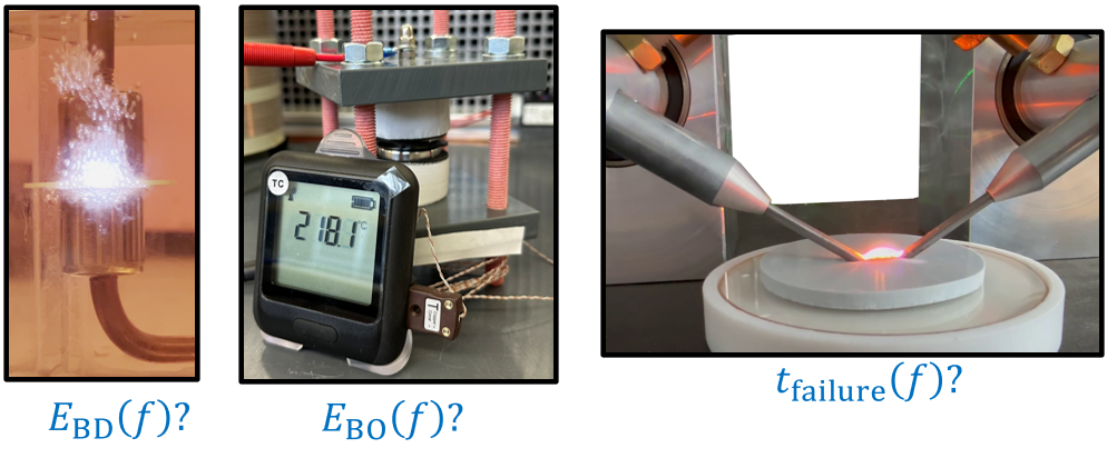
The objective of the Limit Load Test is to determine the maximum stress limits of the materials depending on the respective test voltage or frequency.
The following parameters are evaluated as a function of the frequency of the applied electric field:
1) Breakdown Field Strength
2) Breakover Field Strength (thermal runaway)
3) Arc Tracking Resistance
Long-term Investigations
As part of the long-term studies, the influence of high frequencies combined with high electric fields on the aging behavior of materials is investigated. The focus lies on electrical-thermal multi-stress aging.
Aging tests are conducted both at elevated ambient temperatures and at room temperature. In both cases, the impact of additional heating due to dielectric losses under high-frequency stress is analyzed. Furthermore, a distinction is made between aging with partial discharges and aging without the influence of partial discharges.
Changes in dielectric properties and breakdown field strength are used as aging indicators.