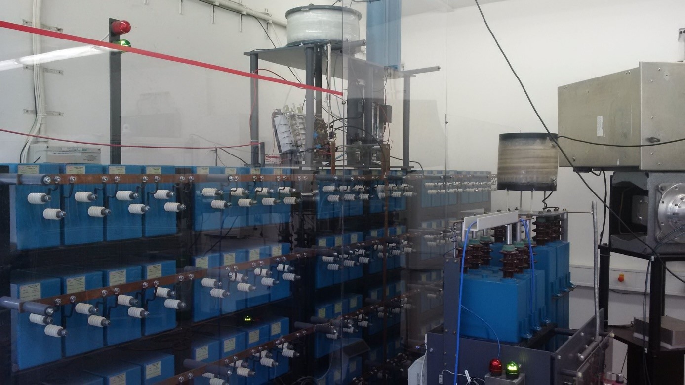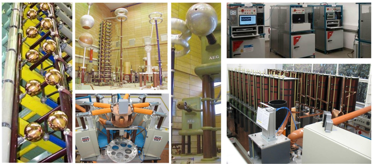
Synthetic test circuit
For investigation of the switching capability of vacuum switches a synthetic test circuit is used.
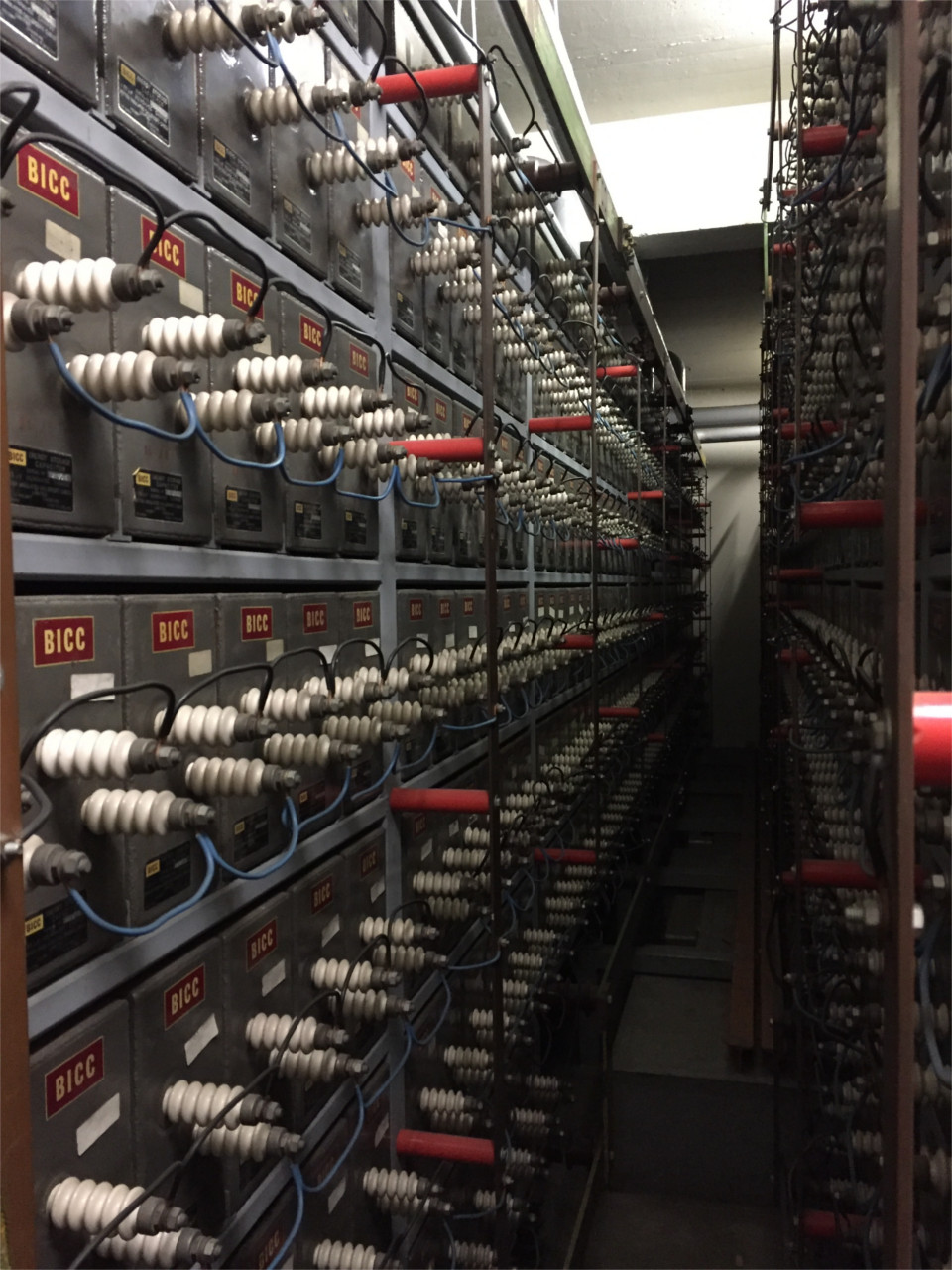
As core element a capacitor bank is available to produce high pulsed currents. With a various set of coils different pulse widths and pulse shapes can performed.
Technical data
Test current: up to 35 kA effective
Current waveforms: 50 Hz sinus, 25 Hz sinus, trapezoidal with 7 ms flat top
Transient recovery voltage: up to 50 kV
Maximum energy: 1,35 MJ
Charging voltage of high current circuit: up to 15 kV
High voltage circuit: up to 30 kV
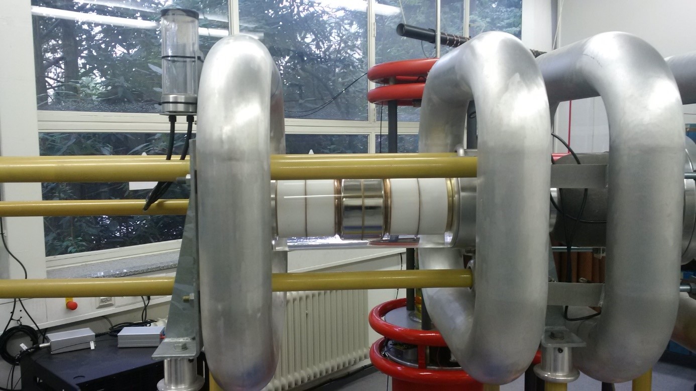
Weil-Dobke circuit
For synthetic tests on circuit breakers a test circuit is used, which is based on the principle of current superposition, also known as Weil-Dobke circuit.
The breaking current is produced by the high current source. The transient recovery voltage is applied to the device under test with a separate high voltage source.
With this setup a breaking test according the standard IEC 62271 and others analyses can be performed.

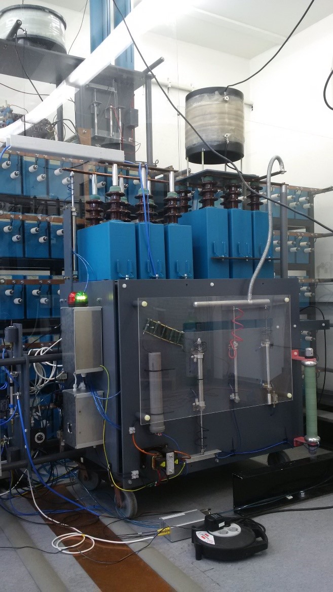
Measurement system
During the investigations several measurement values can be recorded. For this a transient recorder is responsible. For different requirements special measuring channels are available. A rough overview over the technical specifications is given:
- Number of analog channels: 54
- Maximal resolution: 18 bit
- Maximal input voltage. +/- 1 kV
- Maximal sample rate: 250 MS/s
To transfer the measurement data a galvanic insulated fiber optic transmisson line between recorder and user computer is used.
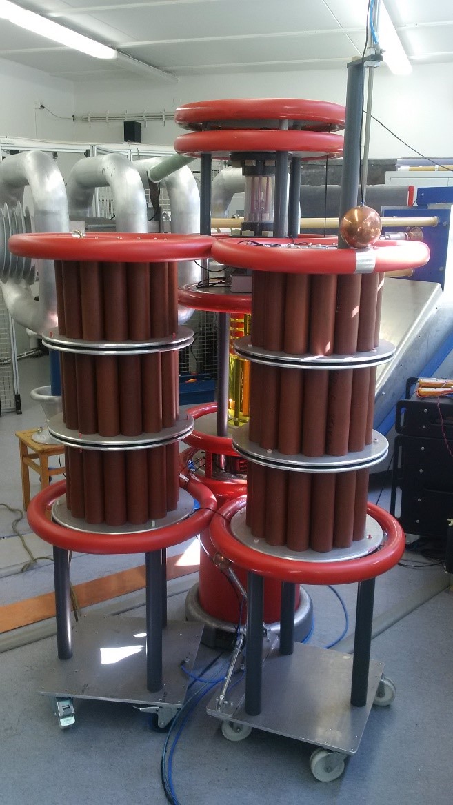
Capacitive switch laboratory up to peak 1.2 kA / 200 kV
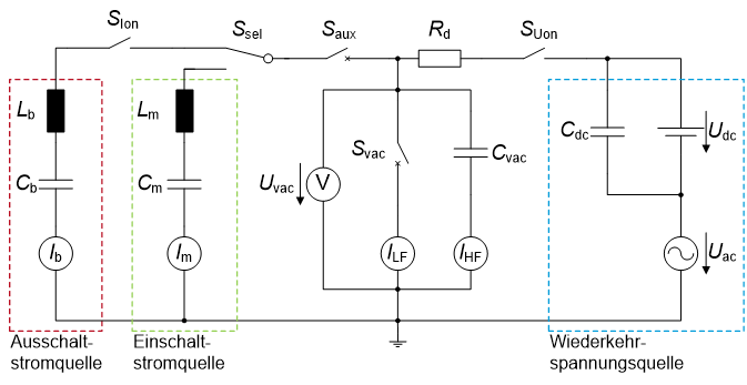
A synthetic test circuit is used to investigate the reignition behavior of high-voltage vacuum interrupters (rated voltage 72.5 kV) when switching capacitive loads.
When switching off capacitive loads, particularly high demands are placed on the dielectric strength of the circuit breakers. After the contact has opened and the arc has been extinguished, the capacitive load remains charged at the maximum voltage of the mains voltage, while the supply side continues to follow the sinusoidal mains voltage curve. The difference between the two voltages is then present across the switching path in the form of a “1-cos” curve as a so-called recovery voltage, the amplitudes of> 2. p.u. can occur. During this time, no flashback are allowed in the circuit breaker. In the synthetic test circuit, the breaking current is provided by a series resonance circuit. A series connection of an AC voltage source and a DC voltage source is provided to generate the “1-cos” -shaped recovery voltage. Several auxiliary switches enable the current and voltage to be switched on at the precise time, as well as a separation between the sources.
Parameters of the switch-off test with a synthetic test circuit:
- Breaking current up to 1.2 kA (amplitude) at 50 Hz
- Recovery voltage (“1-cos”) up to 200 kV (amplitude)
When switching on capacitor banks (in the “back-to-back” configuration), high currents in the kiloampere range with frequencies in the single-digit kilohertz range can occur, which put additional stress on the switching path. In the synthetic test circuit, the inrush current is provided by a series resonance circuit.
Parameters of the switch-on test with synthetic test circuit:
- Exponentially decaying inrush current with 20 kA (amplitude) at approx. 5 kHz
- Pre-ignition voltage of 60 kV